Table of Contents
ToggleChoosing The Best DC MCB For Your PV Combiner Box
The goal of photovoltaic power stations has steadily changed with the rapid development of the technology in recent years, from the original pursuit of pure power generation and scale to the pursuit of a lower cost per kilowatt-hour of the system and a greater level of system safety and reliability.
The first and most crucial step in designing the photovoltaic supporting equipment is to choose goods that must adhere to specifications and have long-term stability in order to increase the safety and dependability of the photovoltaic power generation system. The photovoltaic power station’s power supply comes from the combiner box, which is the first-level confluence device of the solar array. DC MCB is one of the combiner box’s key component.
The accuracy of the DC MCB selection directly affects how reliably the PV combiner box operates. As a result, this article provides some quick introductions to the selection of DC MCBs based on real-world engineering projects as well as pertinent standards and specifications. Please continue reading.
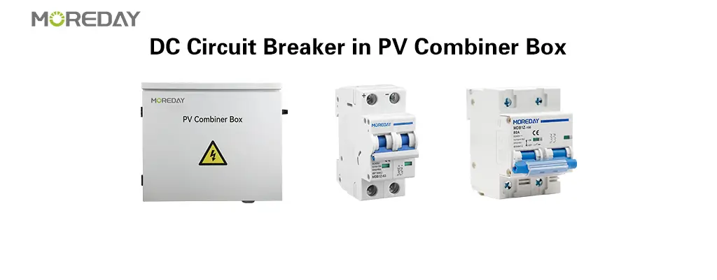
1. Introduction of PV DC MCB
1.1 What purpose does a DC Breaker serve?
Switches known as Circuit Breakers can carry the rated current or adjust the fault current. When a specified amount or limit of circuit current is exceeded, these devices automatically shut down the circuit. The MCB can be manually turned on or off as needed, much like a regular switch.
For DC MCB, the same thermal and magnetic protection principles that apply to AC MCB apply:
When the current exceeds the rated value, thermal protection trips the DC breaker. In this safety mechanism, when the bimetallic contacts are heated, they expand and trigger the circuit breaker. Because the current is so much higher, thermal protection operates more quickly because it produces more heat to expand and open the electrical connection. The DC MCB’s thermal protection guards against overload currents that are just a little bit greater than ordinary operating currents.
When a significant fault current is present, magnetic protection trips the DC breaker, and the action is always immediate. Similar to an AC MCB, a DC MCB’s rated breaking capacity represents the largest fault current that can be disrupted. A DC MCB stops at a constant current; therefore, in order to halt the fault current, the circuit breaker must further open the electrical contacts. DC MCBs’ magnetic protection is more effective against short circuits and faults than it is against overloads.
When there are numerous fault currents present, the magnetic protection in the DC circuit breaker trips the circuit breaker. Even in the worst cases, DC MCBs currently stop the problem. A DC MCB must have magnetic protection since it guards against short circuits and other failures.
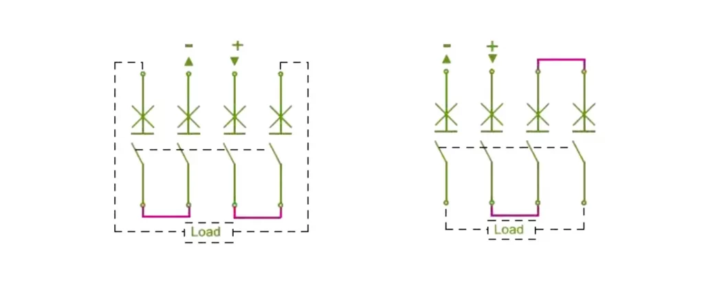
Figure 2-1
Since the photovoltaic DC system’s typical maximum voltage is 1500 VDC, the two series connection options shown in the above figure increase the circuit breaker’s rated voltage in order to meet the DC MCB’s insulation requirements.
2. Selection of PV DC MCB
2.1 Selection of rated voltage and rated current
The DC MCB’s rated operating voltage and rated current I shouldn’t be less than the rated operating voltage and rated current I of the DC bus line and the combiner box, respectively.
As an illustration, consider a polycrystalline module with a 250Wp single power, 20 pieces in a string, and a combiner box with 16 sinks. The combiner box’s rated operating voltage Ue is greater than 20 times the module’s rated voltage, and its rated operating current Ue is greater than 16 times the module’s rated voltage.
The short-circuit current and normal working current differ very little from one another depending on the characteristics of the individual components, so when choosing a DC MCB, 1.25Isc (short-circuit current) is typically used as a guide.
2.2 The influence of altitude on selection
The local atmospheric pressure is lower than the standard atmospheric pressure and the air is thin, which results in a reduction in the strength of the insulating medium as altitude rises. The insulation and rated current of a DC MCB is accordingly reduced because air serves as the device’s insulating medium. Additionally, as altitude increases, so do the insulation capacity and rated current.
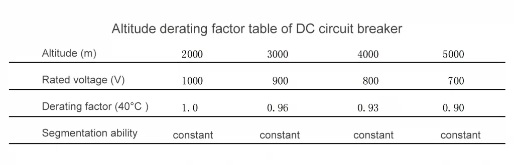
As a result, the DC MCB’s insulating efficacy is reduced. Consider increasing the DC MCB by the corresponding derating factor at this point. The high-altitude derating coefficient table from a particular manufacturer’s selection manual is shown in the table below.

The table shows that derating is not necessary if the photovoltaic DC MCB is utilized at a distance of 2000 meters or less. The derating is extremely visible if it exceeds 2000 meters. Therefore, when choosing DC MCBs, derating must be taken into account when the altitude is above 2000 meters.
2.3 The influence of temperature on selection
The DC MCB’s rated operating current will vary as well as the ambient temperature at which it operates. Additionally, while anti-reverse diodes produce more heat, the majority of combiner boxes come with them.
The circuit breaker must be chosen using the appropriate derating factor if the operating ambient temperature exceeds the intended normal operating temperature.
The table below displays the circuit breaker’s derating factor for the operating environment temperature.
2.4 Influence of wiring form on selection
According to the national standard temperature rise test procedure, 4 meters of copper wire with a rated current cross-sectional area shall be connected in series between the poles for the photovoltaic DC MCB. This connection method uses an external 4-pole pole-to-pole configuration.
This results in the fact that only wires or copper shorting plates that are roughly equal to the length of the phase spacing can be connected between the poles in the combiner box production process due to the volume limit of the combiner box because the cross-sectional area and length of the conductors between the series poles are not specified.
IEC rules state that DC tiny circuit breakers for photovoltaic strings shall have rated current values that comply with 1.25*Isc≤In≤2*IscIsc: the short-circuit current of photovoltaic modules/strings. A derating factor of more than 25% will be produced by DC molded-case circuit breakers linked with short wires, according to the test.
The derating of this connection method should therefore be the main criterion in the selection of photovoltaic DC circuit breakers if the DC circuit breaker in the combiner box uses this approach. This derating factor is around 0.75 times, therefore it must be taken into account.
3. Conclusion
The DC combiner system of the solar power station’s main piece of equipment is the PV combiner box. The DC circuit breaker in the combiner box must be carefully chosen in order to guarantee the combiner box’s safe and dependable operation. The proper selection of the DC circuit breaker requires knowledge of the demands placed on the DC circuit breaker under various environmental circumstances. For the protection and operation of the system, choosing the appropriate DC circuit breaker is crucial. The aforementioned crucial elements must be carefully taken into account, and electrical contractors and installers are urged to reference the manufacturer’s standards and recommendations.

Derek Ke
Hey, I’m Derek Ke, the founder of Moredaydc.com, an expert in solar electrical products and ev charging.
In the past 15 years, we have helped 60 countries and nearly 500 customers (such as farms, residences, industrial and commercial) solve new energy and green power problems. This article aims to share more knowledge about solar electricity and new energy with everyone, so that green electricity can enter every home.
Make Electricity Available To All People